Network Configuration
Network Configuration
The most critical configuration in Untangle is the proper configuration of your network settings in Config > Network. For simple, networks the configuration completed during the Setup Wizard is probably sufficient. However, some networks have multiple WANs, multiple LANs, various subnets, VLANs, VRRP, etc. This describes how networking operates and is configured in Untangle.
Cardinal Rules
There are several key rules to how Untangle operates that should be understood before deploying Untangle in an advanced/complex network.
 |
|
Untangle MUST be installed in-line. Untangle is a gateway product, and it is designed to be in-line with network traffic. Some network administrators want to deploy some of the functionality of Untangle without installing Untangle in-line. This isn't how Untangle is designed and it will likely not work.
For example, Spam Blocker will filter SMTP as it passes through Untangle. It will not store-and-forward to your email server like some products. Web Filter will filter web traffic as it passes through Untangle. It is does not operate as a explicit proxy that you "point" clients' browsers to send web traffic. All applications and functionality are designed to operate in a context where Untangle is installed in-line with the network flow of traffic.
Untangle MUST have a working internet connection. Untangle and many Untangle apps rely on cloud services. Untangle must have a working and consistent connection with the internet. This includes unfiltered HTTPS, HTTP, and DNS access to various cloud services. Without a valid internet connection and configuration many functions of Untangle will not work properly.
Untangle routes ALL traffic according to its routing table. Obviously, this is how all routers operate. They receive packets on an interface and then lookup in the routing table/rules where to send it. Where Untangle differs is that Untangle is often installed as a bridge or with some interfaces bridged together. In the Untangle context, two bridged interfaces share a configuration (some products call them "zones"). Traffic passing between bridged interfaces are still subject to this cardinal rule.
This is often a surprise to people on complex networks as effectively you will need to tell Untangle where to send all the traffic on your network if you want it to go to the correct place. If you have a subnet that Untangle doesn't have a route for, then it will be sent to the default gateway even if that subnet is internal. For Untangle to operate correctly, you must configure Untangle with a complete routing table so it knows how to reach all hosts on your network.
Placing Untangle on the Network
The first step, after understanding the above cardinal rules, is to decide where to place Untangle on the network. Obviously, Untangle must be installed in-line with all network traffic so this provides a two options:
- Install Untangle as the gateway/firewall for the network.
- Install Untangle behind an existing gateway/firewall in flow with traffic.
Installing Untangle as the gateway/firewall is recommended. It is usually the simplest approach and it allows Untangle to leverage its full feature set including WAN Failover and WAN Balancer. This also places it in a convenient place to handle other seperate internal networks (like wireless segments) that may only connected at the gateway. Also, If you have tagged VLANs it is much simpler to run Untangle as a endpoint of those VLANs. This is commonly referred to as router mode.
However, often organizations don't want to replace the existing gateway/firewall or can't because it is controlled by a different organization. In these cases, installing Untangle as a "bridge" behind the gateway allows Untangle and the apps to scan and process network traffic without providing the routing functions of your firewall. This is commonly referred to as bridge mode.
Also, technically you can stick Untangle in front of an existing firewall. Typically firewall/gateways use NAT so all internal hosts share external IPs. This means by the time the traffic reaches the Untangle outside the firewall the source address of all internal communication will have the public address of the firewall. As such, Untangle can not differentiate between internal hosts so much of the functionality of Untangle (web filter, reports, shield, etc) is severely compromised. Installing Untangle outside a NAT device is never recommended.
Configuring the Interfaces
The second major step, after choosing a place to deploy Untangle, is configuring the interfaces. All the configuration options of interfaces are documented in the Interfaces documentation. Likely, External and Internal and are already configured from the Setup Wizard.
After the setup wizard you might still need to do some of the following configuration
- Configure additional subnets on the External/Internal.
Because Untangle routes all traffic according to its routing table. Additional routes/aliases may be required for any additional subnets on your network. More information on that in Installation#Configure Other Subnets
- Configure additional interfaces
After the setup wizard only External and Internal are configured. Additional interfaces are disabled and still require configuration. More information on that in Installation#Configure Other Interfaces
- Configure any tagged VLANs
If you have tagged VLANs (802.1q) on your network. You will need to add VLAN Tagged Interfaces.
Bridging
When two interfaces are bridged in Untangle this means they are effectively sharing a configuration. Some products use the concept of "zones." In this terminology, bridging two interfaces puts those interfaces in the same "zone" or "network space."
Standard Bridge Mode
The most common scenario this is used is in bridge mode where the External is bridged to the Internal. This is extremely useful when there is a firewall upstream.
For example, if the firewall is 192.168.1.1, then you can configured External as 192.168.1.2/24 with 192.168.1.1 as the gateway. The internal hosts all have 192.168.1.* addresses and can continue to use 192.168.1.1 as a gateway (192.168.1.2 will also work as a gateway).
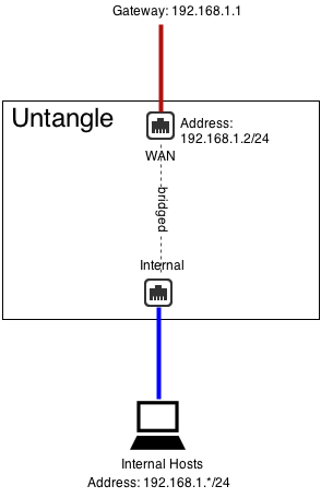
It is important to remember that even when bridging Untangle routes ALL traffic according to its routing table. This means if you have other subnets besides 192.168.1.* like 192.168.2.*, then you will need to add aliases or routes for them otherwise that traffic will go to the default gateway.
DMZ Bridge
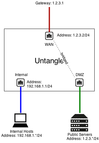
Another common scenario to use bridging is when Untangle has a public IP (1.2.3.2 in this example), but you have other public servers with public IPs (1.2.3.*). You could put those servers on the private network and use Port Forward Rules. But lets assume you wanted to keep them configured with public IPs to keep them separate from the internal and avoid any NAT/port forwarding issues.
In this case, you can bridge a "DMZ" interface to your external and it essentially shares the configuration and "zone" with external. This means you can place servers with public IPs on that segment and they can continue to use 1.2.3.1 as a gateway.
Additional Port
You can also just use bridge mode to provide alternate ports to existing interfaces/zones. Be careful, as traffic between the two goes through Untangle!
For example, if Interface 2 is configured as 192.168.1.1/24 and Interface 3 is bridged to Interface 2, then they are both effectively 192.168.1.1. Basically Interface 3 becomes an additional port for the Interface 2 network.
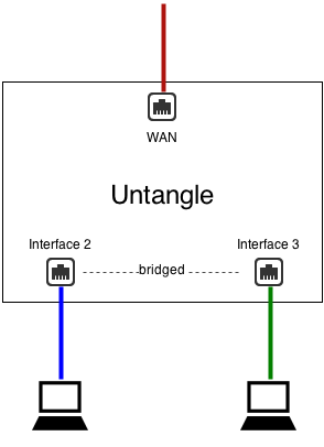
This is almost identical to a configuration without Interface 3 where Interface 2 is plugged into a switch with two free ports.
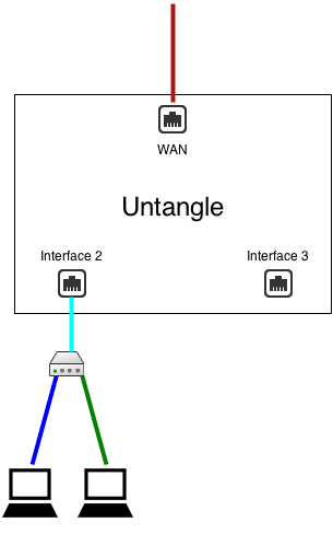
There are some important differences:
- In scenario 1, traffic between Interface 2 and Interface 3 goes through Untangle and is routed via Untangle's routing table
- In scenario 1, traffic between Interface 2 and Interface 3 goes through Untangle and is scanned by the apps (if not bypassed via Bypass Rules)
What "bridged" really means.
In untangle when two interfaces are bridged it means that they are in the same zone or that they both connect to the same network space. As the cardinal rules explain, Untangle routes all traffic according to its routing table - even those crossing between two bridged interfaces. This is sometimes called brouting or a brouter - unlike how a traditional layer-2 bridge/switch behaves.
It means that packets coming inside one side of a bridge will NOT necessarily exit the other side of the bridge. It also means that packets destined with a specific route will be routed according to Untangle's routing table. All traffic is routed according to Untangle's routing table. It also means MAC addresses are not maintained across segments, even if they are bridged together as packets are brouted.
This may cause you to wonder how Untangle works in the traditional "Bridge Mode." The answer is simple, for outbound traffic to the internet untangle will route that to its default gateway which was probably where the traffic was headed anyway and definitely where it should go. For inbound traffic Untangle knows the where each local host on the bridged segment lives and it routes it directly. So inbound and outbound traffic both flow as expected.
Where things get complicated is when networks have more complicated routes and do not configure Untangle with those routes. Assume Untangle is installed in traditional bridge mode on a 192.168.1.1/24 network. Lets assume the network also has another internal network of 192.168.2.1/24 behind an internal router 192.168.1.100. There is probably already a route on the existing firewall telling it that 192.168.2.* can be reached behind 192.168.1.100. If the user then inserts untangle in bridge mode and configures it as 192.168.1.2, the entire 192.168.1.* network will work but none of the traffic on 192.168.2.* will work. Why? Because Untangle routes *all* traffic according to its routing table. The firewall will route 192.168.2.* traffic to 192.168.1.100. When that traffic passes through Untangle it will not route it to 192.168.1.100 - it will route it according to its routing table. Since it knows nothing about 192.168.2.* and those addresses aren't local, it will be sent back out to the default gateway. As such the 192.168.2.* network will be completely offline as return traffic from the internet will not reach those hosts. Once a 192.168.2.0/24 route to 192.168.1.100 is added to Untangle traffic will flow as expected. The routing table on Untangle must reflect the layout of the network.
Another common scenario is bridging two separate networks with one Untangle server. Lets look at an example with 4 interfaces: network1External, network1Internal, network2External, network2Internal. network1Internal is bridged to network1External. network2Internal is bridged to network2External. The problem with this scenario is that Untangle routes all traffic according to its routing table. If traffic comes in on network2Internal and is bound for the internet it will NOT be sent out network2External just because that's where it was originally headed. It will be routed according to Untangle's routing table, which is the default route of Untangle - probably network1External's gateway! To setup this scenario one must use WAN Balancer and routes to assure that traffic coming in network2Internal is routed via network2External. This is true whether or not the separate network or separate physical networks or separate VLAN networks.
The key to using bridge mode effectively is understanding how Untangle routes traffic. While bridging can often be convenient it can also create headaches for complicated setups.
NAT
NAT or Network Address Translation is the operation of rewriting the source address of packets. Typically this is used so many internal hosts with internal IPs (192.168.*.*, 10.*.*.*, etc) can share one or several public IPs.
There are 3 ways that NAT is done is Untangle:
- If you check NAT traffic exiting this interface (and bridged peers) on any WAN interface configuration.
- If you check NAT traffic coming from this interface (and bridged peers) on any non-WAN interface configuration.
- If you add a NAT Rule
NAT traffic exiting this interface (and bridged peers)
The first option is NAT traffic exiting this interface (and bridged peers), as described in the Interfaces documentation, will NAT any traffic exiting this interface and any of its bridged peers. This is the enabled by default on all WANs, and is enabled if Untangle is installed as a router via the Setup Wizard.
What this means is that any and all traffic exiting that WAN interface or bridged peers will be NATd to auto which is the current primary address of that WAN interface. Traffic between this interface and any bridged peers will not be NATd. Checking this option also blocks all traffic coming to this WAN that is not to a local process or explicitly forwarded with a Port Forward Rule.
NAT traffic coming from this interface (and bridged peers)
The second option is NAT traffic coming from this interface (and bridged peers), as described in the Interfaces documentation, will NAT any traffic coming from this interface and any of its bridged peers. This is not enabled by default.
What this means is that all traffic from this interfaces will get NATd to auto which is the primary address of which ever interface the traffic it exits. Traffic between this interface and any bridged peers will not be NATd. Checking this option also blocks all traffic to this non-WAN except traffic forwarded with a Port Forward Rule.
When and Where to perform NAT
If there are only two interfaces in Untangle the first and second options are identical. When there are multiple internal subnets you will need to configure where you wish to NAT so that you have the desired behavior.
If you wish internal networks to be able to speak with each other (ie 192.168.1.100 should be able to reach 192.168.2.100 on a different interface) then you do not want to NAT between those networks.
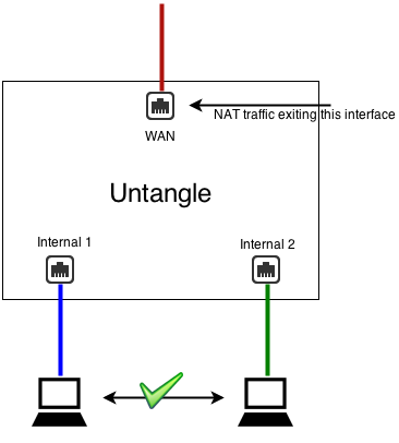
As such, you should uncheck NAT traffic coming from this interface (and bridged peers) on both LAN interfaces, and check NAT traffic exiting this interface (and bridged peers) on the WAN(s).
If you wish for internal networks to be completely separate such that they can not speak to each other then you want to check NAT traffic coming from this interface (and bridged peers) on the non-WAN interfaces. This means NAT will be performed on all traffic from these LANs and inbound sessions will be blocked unless explicitly forwarded with Port Forward Rules.
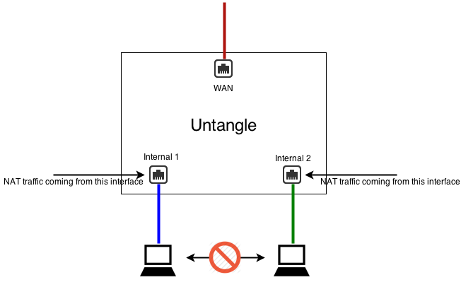
NAT Rules
The third option is explicitly configuring exactly what should be NATd to what address with NAT Rules. Be aware, these rules do not also explicitly block any inbound traffic like the two NAT options. NAT rules can be used in conjunction with the two NAT checkboxes and any matched NAT rule will take precedence. Most networks need only one the first two options, but sometimes there are scenarios where a NAT rule is wanted desired such as 1:1 NAT or when you want to guarantee that certain traffic (like SMTP exiting an email server) uses another address other than the primary WAN address.
If no NAT option is enabled (all unchecked and no NAT rules) then Untangle will route like a typical router without performing any NAT operation.
Note: The NAT traffic exiting this interface (and bridged peers) option in WAN is equivalent to appending an Auto NAT rule to the end of the NAT Rules matching all traffic with Destination Interface equal to that WAN or any bridged peer but excluding traffic between any bridged peers in that zone. It also includes a forward filter rule to block inbound sessions from this WAN or bridged peers not explicitly port forwarded excluding sessions between any bridged peers in that zone.
Note: The NAT traffic coming from this interface (and bridged peers) option in WAN is equivalent to appending an Auto NAT rule to the end of the NAT Rules matching all traffic with Source Interface equal to that non-WAN or any bridged peer but excluding traffic between any bridged peers in that zone. It also includes a forward filter rule to block inbound sessions to this non-WAN or bridged peers not explicitly port forwarded, excluding sessions between any bridged peers in that zone.
VLANs
VLANs or Virtual LANs are commonly used so that multiple subnets can share the same wire while maintaining complete separation including separate broadcast domains.
IMPORTANT:
The term VLAN is sometimes also used to describe putting multiple untagged (no 802.1q tag) subnets on the same wire. For example, Untangle is in bridge mode as 192.168.1.2/24 but there is also a 192.168.2.* on the same wire. If there are no 802.1q tags on the 192.168.2.* traffic - it is NOT a VLAN and new VLAN interfaces should NOT be created on Untangle. In this scenario you should use guidance in Installation#Configure Other Subnets to properly configure Untangle to handle these subnets. VLAN interfaces will ONLY handle tagged 802.1q packets and all packets sent to a VLAN interface will be tagged with 802.1q tags.
VLANs have several uses. Often you want multiple completely separate internal subnets on a network, but you do not want to run multiple physical ethernet networks through a building. VLANs allow you to run multiple networks on the same physical wire while still guaranteeing they are completely separate and secure. To do this you must have VLAN enabled switches and products through-out the network. VLANs can also be useful if you have limited ethernet ports on Untangle and wish to overload a single NIC with two separate purposes. This requires that NIC to be connected to a VLAN enabled switch.
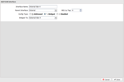
To create a VLAN interface click on the Add Tagged VLAN Interface button at the bottom of the interfaces grid on the Config > Network > Interfaces. This will create a new virtual interface. First, you will need to give this interface a new name, and also select the Parent Interface. The Parent Interface is the physical interface that this VLAN virtual interface exists on. Then you will need to configure an 802.1q Tag which is an integer between 1 and 4094 inclusive. After this you will configure the interface just like any interface.
This new VLAN interface is just like a physical interface in all ways. This means you can configured this VLAN interface exactly like any physical interface. It is completely separate from the physical parent interface. Any packet coming in on the physical parent interface with the 802.1q tag matching the configured value (1-4094) will be considered by Untangle to be coming in the VLAN interface. Any packet sent to the virtual VLAN interface will actually be sent on the physical parent interface with the configured 802.1q tag. All untagged packets on the physical parent interface will be processed like normal through the physical parent interface, only 802.1q tagged packets with the matching 802.1q tag will be processed by the VLAN interface.
After configuring Untangle with the appropriate tagged VLAN interfaces, you will need to configured some VLAN-enabled managed switch to properly process the packets as desired. For example, here is a document describing how to configure a HP procurve switch.
Note: VLAN interfaces are completely separate from their physical parents, however they do share the same physical NIC and as such will be limited by the throughput of the physical NIC. For example, if you have two 100Mbit tagged VLAN WANs on the same physical 100Mbit NIC, then you will still be limited to 100Mbit total on both WANs at any given time.
Example: We want to have two completely separate LANs on our network but we only have one wire or one network card. As such we need a VLAN enabled switch. Configure the internal interface with the IP and configuration from LAN 1. Create a tagged VLAN interface with 802.1q tag 3. Configured the new VLAN interface with the IP and configuration for LAN 2. Now configure your VLAN switch to send VLAN 3 packets to the appropriate ports with LAN 2 hosts. In this scenario we are using the same wire but have two separate LANs with separate broadcasts domains.
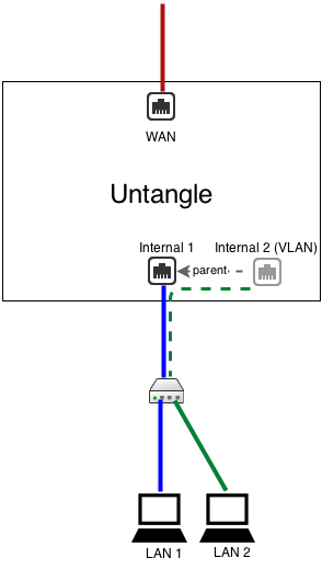
Note: If you want to use a single wire and/or network card but you don't care about keeping the two LANs seperate, you don't need VLANs and can just use aliases/routes.
Configuring VLAN on Untangle in Bridge Mode
Some users want to configure untangle in bridge mode in the middle of a VLANed network. This is possible, but NOT RECOMMENDED. It is suggested to install Untangle as the gateway and terminate VLANs on an addressed VLAN interface. However, if you wish to install Untangle as a bridge in the middle of several (V)LANs simultaneously, the following instructions will allow you to establish multiple bridges and then enter the routes to tell Untangle that if traffic enters on a specific interface it should exit the bridged peer.
- You will need to create 2 virtual interfaces for each VLAN you want to set up.
- One as a child to the external interface
- One as a child to the internal interface
- To set up the external's VLAN interface
- Click on Create a tagged VLAN interface
- Give the interface a name that's easily identifiable by you
- Set the Parent Interface to External
- Set the 802.1q tag
- Config type must be "Addressed"
- Under IPv4 configuration, assign a unique static IP to the interface.
- Enter the IP address for the VLAN gateway
- Enter DNS servers you would like to use
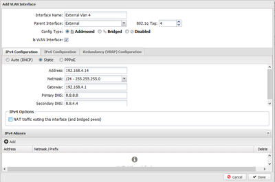
- To set up the internal's VLAN interface
- Click on Create a tagged VLAN interface
- Give the interface a name that's easily identifiable by you
- Set the Parent Interface to Internal
- Set the same 802.1q tag that you configured on the external VLAN interface
- Config type must be "Bridged"
- Bridge this interface to the external VLAN interface
- Go to WAN Balancer and set the weights to send 100% of network traffic out of your untagged external interface
- Click over to the Route Rules tab and create a new rule
- Source Interface : [Internal VLAN interface]
- Destination WAN : [External VLAN interface]
VRRP
VRRP provides network level redundancy.
Multiple Untangles can be run in parallel in a high availability configuration. In this configuration one Untangle will be the "master" and one or more Untangles will be the "slaves." In the event the master fails, one of the remaining slave Untangles will take over the master role such that network traffic continues to flow without interruption.
Untangle uses VRRP or Virtual Redundancy Router Protocol to handle the switching between Untangle servers. All Untangle servers must be on and all configured with a share VRRP Virtual Address. The master is the only Untangle to answer/handle traffic routed to the VRRP Virtual Address. If the master fails an "election" is held over VRRP and the next highest priority slave will begin handling traffic to the VRRP Virtual Address.
All Untangles interfaces must be configured statically, and there must be no bridged interfaces. Parallel Untangles configured as bridges will create a bridge loop!
VRRP Basic Example
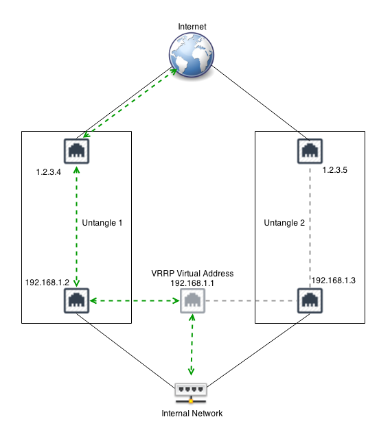
A common configuration is running two Untangles to act as the gateway for the internal network. For example, lets assume Untangle 1, the master, has a public IP of 1.2.3.4 and an internal IP of 192.168.1.2. Lets assume Untangle 2 has a public IP of 1.2.3.5 and an internal IP of 192.168.1.3. Both are running in "router" mode and doing NAT and acting as a gateway. Note that all IPs must be unique! This configuration requires each untangle to have its own external IP!
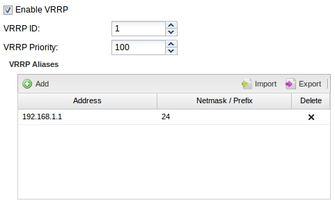
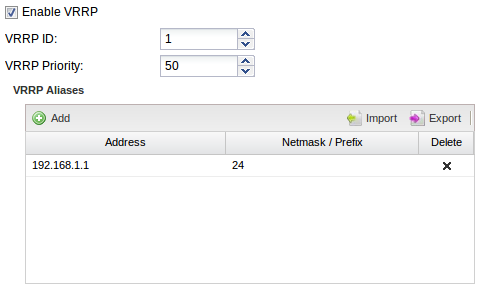
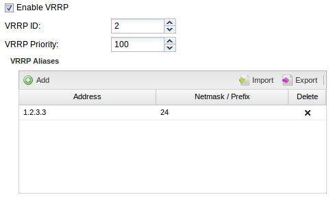
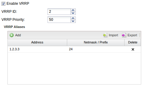
Now we configure Untangle 1 to have a VRRP Virtual Address of 192.168.1.1 on the Internal interface, and also configure Untangle 2 to also have a VRRP Virtual Address of 192.168.1.1 its Internal interface They both share the same VRRP Virtual Address. Each Untangle in the group must have the same VRRP ID. So lets give Untangle 1 a VRRP ID of 1 and also give Untangle 2 a VRRP ID of 1. We want Untangle 1 to be the master when its on and working without issues so give it a higher priority of 100. Untangle 2 is the slave so it should be given a lower priority so lets give it a lower priority of 50.
Configure your internal hosts to use the VRRP Virtual Address (192.168.1.1) as the gateway. In this configuration the master will route all traffic to 192.168.1.1 just like a regular address. Should the master fail within a few seconds the slave will become the new master and start routing traffic.
Note: You should configure the DHCP server to hand out 192.168.1.1 as the default gateway. If untangle is providing DHCP. Configure Untangle 1 as the "authoritative" with 192.168.1.1 as the "Gateway Override." Configure Untangle 2 the same but as non-authoritative. This way Untangle 1 will handle all DHCP unless it is down, in which case Untangle 2 will handle DHCP.
VRRP External Example
The above example work great for outbound traffic, but if you have inbound traffic being port forwarded that traffic might fail if the Untangle owning that address fails. VRRP can also be used to provide redundancy for inbound traffic. For example, similar to above, lets assume you have Untangle 1 with 1.2.3.4 and Untangle 2 with 1.2.3.5.
You can configure both with a shared VRRP Virtual Address of 1.2.3.3. Now configure port forwards on both Untangle for traffic destined to 1.2.3.3 to the appropriate internal host. Only the master will handle traffic to 1.2.3.3. If the master fails the slave will take over traffic handling for 1.2.3.3 and port forwarding. External hosts will still be able to reach local services should the master fail.
In this scenario NAT Rules can also be configured if outbound traffic should use the same address regardless of which server is handling the traffic.
VRRP Combined Example
It is also possible to combine VRRP on multiple interfaces. For example, combine the above two examples. VRRP can be used to provide redundancy on both interfaces. VRRP IDs must be unique for each server. For example, the external on both should be VRRP ID 1 and the internal on both should be VRRP ID 2. In this scenario VRRP is "grouped" such that if the server loses its "master" status on one interface it will also release its master status on other interfaces.
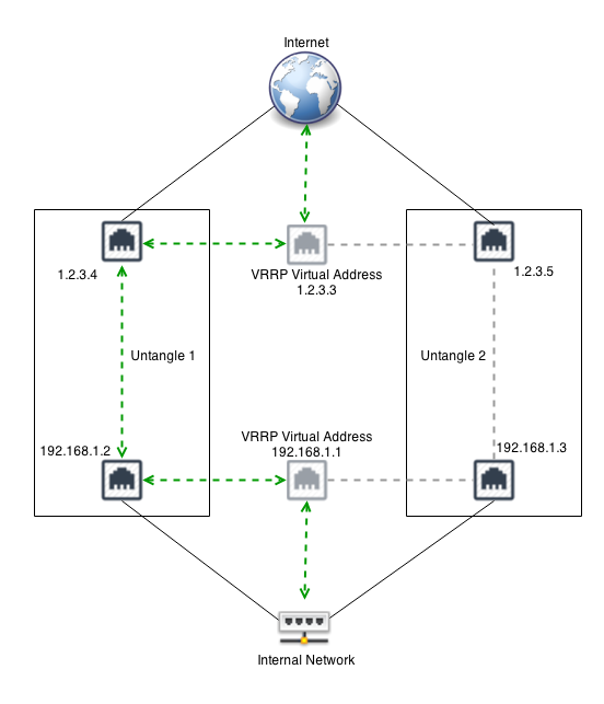


For example, in the picture above if the Internal interface on Untangle 1 is unplugged, then Untangle 2 will become the master and start responding to 192.168.1.1.
Untangle 1 will also release its master status on the external interface so that Untangle 2 will also handle 1.2.3.3. This is to avoid any scenarios where Untangle 1 is master the external address and Untangle 2 is master on the internal address.
VRRP FAQs
What kind of problems count as a failure for VRRP purposes?
Most critical hardware issues such as power outages, crashes, or freezes will immediately cause the VRRP broadcast to stop and the slave will immediately take over. Furthermore, if some common errors are detected in software such as the NIC being unplugged then the VRRP broadcast is stopped.
How can I see which is the VRRP master?
The VRRP status is available in the VRRP settings. The Is VRRP Master? indicator will be green if master.
How can I test my VRRP configuration?
Simply configure VRRP then unplug one of the VRRP Untangle interfaces. The slave should immediately take over and you should still be able to ping the VRRP Virtual Address.
How quickly does traffic switch?
VRRP acts very quickly in the case of a failure and usually switches in less than a few seconds. However, TCP sessions will be reset as state is lost.
No. There is zero state sharing between Untangle. The session tables are separate, so sessions will be reset if the slave takes over. Furthermore application data is not shared or synchronized between servers. This includes things like host tables, captive portal logins, openvpn state, ipsec state, email quarantines, reports, quotas & penalty boxes, web filter bypass states, antispam learning, etc.
Can I run VRRP in bridge mode?
No. "Slave" untangles are still live, they just do not handle traffic to the VRRP Virtual Address. As such if any bridge loop is created with bridged interfaces between the master and slave the network will stop functioning.